In my
last post I talked mostly about wanting a
Sturmey-Archer AW three-speed hub and then actually acquiring one. Now, I'm going to relate my experience rebuilding the hub. Or rather, for now, the disassembly of the hub.
I'll start by saying I didn't go into it completely blind. As I had mentioned, I had a little experience rebuilding the actual inner workings using a hub a coworker had acquired and disassembled. He had found a wonderful
PDF scan of the "
Sutherland's Handbook of Coaster Brakes and Internally-Geared Hubs" section for the AW three-speed hub on Sheldon Brown's website. I had tried making sense of the written guide on
Sheldon Brown's website, but found the pictures and exploded view of the Sutherland's scan to be exactly what I needed. I disassembled my hub without the guide, as that is rather easy, and only occasionally referenced it during the rebuild, to make sure I oriented things in the proper way. I heavily recommend the Sutherland's scan for any internal work.
 |
Top Left: Non-drive hardware.
Top Right: Lubrication port, hub flange, and sprocket.
Bottom Left & Right: Drive-side assembly and hardware.
All prior to cleaning.
Taken July 10, 2013 |
I was, of course, very anxious to start disassembling it and tried to start in my apartment but did not get very far. I was able to remove the snap ring which keeps the sprocket and sprocket spacers on, along with the dust cap under that, but that was all I could remove.
 |
Left to right: Drive side hardware, snap ring, both sprocket spacers, the sprocket itself, and the hub.
Taken on July 11, 2013 |
The hardest part of disassembling one of these hubs, in my opinion, is removing the ball ring. The ball ring is the part of the inner assembly that actually threads into the hub shell, holding it all together. These are almost always incredibly tight, and the commonly accepted procedure is to actually place a punch on one of the two notches cut into the ball ring and hammer it loose. Once loose, a lock ring spanner or your fingers can unthread it. The problem is that it is also recommended to have the hub laced to a rim to do this, to keep the hub secure and in place. Otherwise, you need a vise to clamp the hub shell as you whack away on it. I only had the bare hub, and no vise. My eager-to-help fiancee
Keri tried holding the hub as I pounded on it but to no avail; these things are just tight. I'd have to bring it into work to use the vise there.
I had dowsed the hub with WD-40 at home to try and lessen the friction on the threads. It didn't work. The next day in the shop, I planted the hub in our vise, with the handy aluminum jaw covers so as to not dent or scratch the steel shell, and went at it with a hammer and screwdriver. Nothing. I did this a few times throughout the day and got nowhere. I was starting to get frustrated. Every time I beat on it, the whole hub would shift backwards in whichever direction I was hammering. I tried more WD-40: nothing.
Finally I checked my phone for an old text message with my fellow Sturmey-crazy coworker and noted he said to use
PB Blaster, a really effective penetrating lube. I sprayed some of this stuff on the hub, let it sit for less than a minute, and anxiously put my screwdriver and hammer to it. Nothing moved. For a moment I was disappointed, when something flared up in the back of my mind.
Nothing moved. The hub did not shift backwards. It stayed exactly where it was in the vise. This meant that the force of my hammer was breaking the friction of the threads, and not just moving the hub within the vise. Eureka! With a few more whacks and a lock ring spanner, I triumphantly unthreaded the assembly. What a feeling!
 |
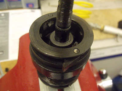
The vised hub, with PB Blaster visibly resting on the ball ring. Note the shallow notch on the
right side that I was hammering into.
Taken on July 11, 2013 |
I'll take a quick moment to note that the ball ring actually taught me about something I didn't know existed: double start threads. I looked it up and was amused to discover double start threads are basically a pair of threads that can start opposite or next to eachother. They are used when you want a piece to thread quickly over a short distance, but you want it to also be a very precise threading. With a "normal" single start thread, you can achieve this by broadening the pitch of the threads, but then you have a very clumsy or slopping threading. I just thought this was neat, as I'd never heard of anything like it.
 |
A little hard to see, but you can barely make out the double start thread on the ball ring.
Taken on July 11, 2013 |
 |
Removing the inner assembly.
Taken on July 11, 2013 |
 |
Left: The inside of the hub shell. Note the machined surfaces for the ratcheting pawls. And the glob of grease.
Right: The removed inner assembly, vised and ready to be taken apart.
Taken on July 11, 2013 |
The first thing to do with the removed assembly was to unthread the drive side cone and locknut. Underneath the cone is the clutch spring and its cap. The clutch spring puts pressure on the clutch, wanting to return to the high gear. When you shift down and pull cable, you're pulling against the spring. This means that when you do the opposite and shift up, into higher gears, you're letting the spring push the clutch back to where it wants to go.
 |
The clutch spring and its cap, free at last.
Taken on July 11, 2013 |
Thankfully the clutch spring is not attached to anything and just rests inside of the assembly. It's easily removed. Next is the driver, one of the more uniquely shaped parts. The driver has quite a few jobs. First and foremost, the driver is what the sprocket connects to, hence giving it its name. It is also, in a sense, a giant cone, resting on a third set of bearings inside the ball ring, which we'll see later. Lastly, the clutch interfaces directly with the driver in the middle gear.
 |
The driver. Note the notches cut in the lower half for the clutch and the three grooves on
the top half which the sprocket slides onto.
Taken on July 11, 2013 |
The driver is also kind of unique because it is both a cup and a cone. It is a cup for the axle, and a cone for the inner assembly. You don't really find that very often. The nefarious ball ring holds the bearings that the driver rests on. This set of bearings is what allows the hub to freewheel, such as when coasting and not pedaling. Aside from also attaching the entire inner assembly onto the hub shell, as mentioned before, it also has machined surfaces on the inside for the first pair of ratcheting pawls found in the assembly.
 |
The ball ring, named so because it houses the third set of ball bearings in the hub.
Taken on July 11, 2013 |
 |
The machined surfaces for ratcheting, on the inside of the ball ring. Similar to the inside of the hub shell, as seen above.
Taken on July 11, 2013 |
Now we are starting to get to the good stuff! Next is the gear ring, which also has a pair of pawls to interface with the machined surfaces of the ball ring. But perhaps more importantly, the inside of the gear ring is toothed and meshes with the four planet gears on the outside of their orbit, while the sun gear of the axle meshes with them on the inside. It is one of the three parts that comes together to create the planetary gear system that makes this whole thing actually work. If you're confused on how the planetary gear system actually works, don't fret. I will explain that in the next post.
 |
The outside of the gear ring, from the top. Note one of the two pawls, which interfaces with the inside of the ball ring.
Taken on July 11, 2013 |
 |
The inside of the gear ring. Pretty cool huh? This is where the planet gears mesh. Note the four raised "dogs" also on the inside, near the inner edges of the pawls. These are important too.
Taken on July 11, 2013 |
With the gear ring removed, we can start to see the true inner workings. A lot of different parts are visible with the gear ring gone, and they're all very important. First, on top is the clutch. This plus-shaped piece of metal is what moves when you pull or release cable with the shifter. In each of the three gears, it does something important. I'll explain how all of that works in the following post. For now, know the indicator chain slides into the hollow axle and threads into the axle key (see below), which then allows the clutch to move back and forth inside of the assembly as you use the shifter.
 |
The small plus-shaped assembly is the clutch. Note how it is interfacing with the raised gear pins. This is
crucial to your high gear.
Taken on July 11, 2013 |
 |
The four pieces that come together to become the clutch. Clockwise, starting from the top left: thrust ring, axle key, clutch sleeve, and the clutch itself.
Taken on July 11, 2013 |
Underneath the clutch is the planet cage. In a way, this is where it all begins. The planet cage houses the planet gears, which are between the sun gear of the axle, and the gear ring introduced above. On the bottom of the planet cage are the second pair of pawls, which interface with the hub shell.
 |
The planet cage. Note the planet gears and the raised pins which secure them.
Taken on July 11, 2013 |
 |
The planet cage and removed planet gears. The gears are so precisely machined, you can't help but love them.
Taken on July 11, 2013 |
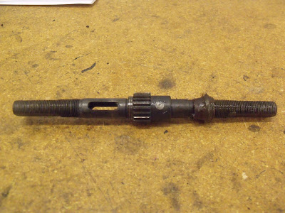
Finally, with the planet cage and planet gears gone, all that remains is the bare axle. In the middle of the axle is the sun gear, which meshes with the planet gears which mesh with the gear ring. It is pretty important in all of this. The axle also has a slot milled into it, for the axle key component of the clutch to slide back and forth within. Interestingly, on this axle there was a rather thick glob of grease hiding beneath the planet cage. That was wiped off.
 |
The final part: the bare axle. Note the central sun gear and the slot which the axle key slides up and down, thus moving the clutch. Oh, and the extraneous glob of grease. Ew.
Taken on July 11, 2013 |
With all of the parts disassembled, I set them all in the shop's parts cleaner and let them soak overnight. These machines actually don't run on a lot of grease, which may seem surprising. Truthfully, all of the grease is with the bearings, as usual. The inner assembly uses a high quality oil as a lubricant. Anything with ratcheting pawls typically doesn't use a grease, as the grease tends to not let the pawls do their job. That being said, the inner parts were not that dirty and I could have put them all back together right there and no one would ever know the difference. But for my own satisfaction, I wanted to clean everything and try to start over from scratch, or at least as close to scratch as I could. After letting everything soak overnight, I hit the parts with the ultrasonic waves a few times, used a few cans of elbow grease, and finally had a bin of clean and gleaming parts. Excited, I took everything home to reassemble at my leisure.
And so, the next post will detail the reassembly, and most interestingly of all, I will attempt to explain how these machines work. Enjoy.


